



Introduction:
I would like to introduce a truly “classic” PLC programming method that is highly effective in practice but that, as far as I can tell, few of you know about: the sequential programming method.
As its name suggests, this method is effective for programming sequential control processes, where step 1 finishes before moving on to step 2, and so on through step n. This makes it extremely effective for programming the stations in the MPS course in Mechatronics.
First, let me outline the advantages of this method to get you interested. The first is that programs written this way are very easy to write and read. Once you know how, you can write them very quickly (mostly just copying, pasting, and editing). Second, this method does not use SET or RESET. If you have programmed PLCs before, you will know that using SET and RESET requires very tight control over the program flow. Otherwise, they can “conflict” with each other and cause errors immediately. Third, this method is highly effective (which is why I called it “classic”). For the PLC Practical Training course in particular (exercises involving pneumatic cylinder pistons), or MPS, this is the “number 1” method!
Enough of the sales pitch; now let me explain how to program using this method.
Theory:
Step 1: Write out and summarize the operating sequence. You may be given the sequence in the assignment or in the requirements provided by your instructor, or you may need to write it yourself based on the actual requirements of the control task (for example, in the MPS course, you need to write it based on the operating sequence of each station). Use short, memorable symbols to summarize this sequence.
Divide the sequence into stages (each stage simply performs one action or several parallel actions taking place at the same time).
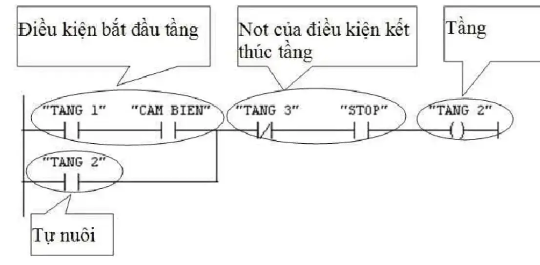
Step 2: Program the temporary memory bits to remain energized (marking the stage currently being executed). This step is carried out as follows:
First, define the condition for starting a stage. A new stage usually starts when the previous stage has completed its task. For example, stage 2 starts when stage 1 is active and a particular limit switch is actuated (indicating that the task is complete).
Next, take the NEGATION (NOT) of the conditions for ending that stage (usually when the next stage starts or when the Stop or Reset button is pressed). Let me also remind you of De Morgan’s laws:
~(A.B.C) = ~A+ ~B + ~C
~(A+B+C) = (~A).(~B).(~C)
For example, the condition for deactivating stage 2 is: stage 3 is active OR the Stop button is pressed. As an expression, this is: DKNT = TANG3 + STOP. The NEGATION of this condition is therefore ~DKNT= ~TANG3 . ~STOP. In words, this is (NOT TANG3) AND (NOT the STOP button). NOT TANG3 is always a normally closed (NC) contact, whereas NOT the pushbutton depends on the type of pushbutton used.
(This image is for a normally closed NC Stop button.)
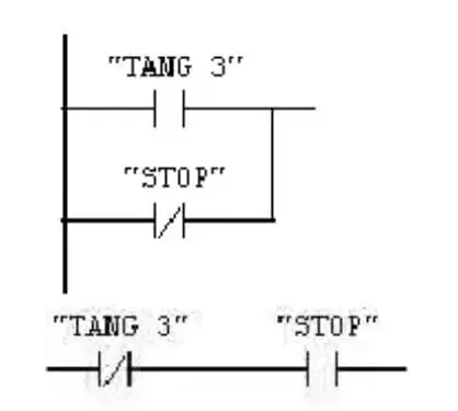
The condition for deactivating stage 2 and the negation of that condition
Finally, use a contact to make it self-holding. Place this contact in the program in parallel with the condition for starting the stage.
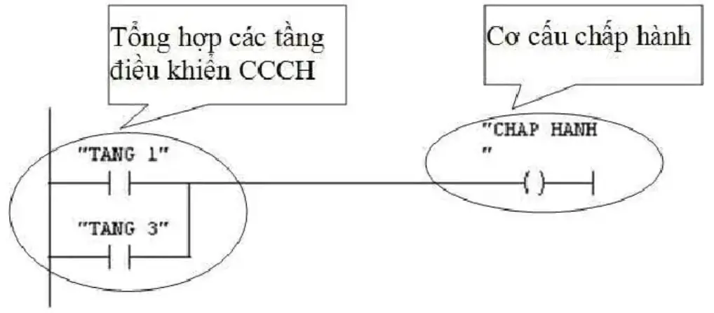
Step 3: Combine the conditions for the physical outputs (the actuators). Suppose TANG 1 and TANG 3 operate an actuator.
Practical example:
Let us use station 1 of the MPS system as an example to write a program and explain it so you can visualize it more easily. (If you are not a Mechatronics student or have not worked with this station, do not worry; I will explain it in detail.) Also, to be clear, the operating sequence for this station was defined by the author (so it may not be the same as the one used in class!).
Hardware explanation: This station supplies workpieces.
* The station has 3 actuators:
A pneumatic cylinder pushes out and clamps the workpiece. This cylinder is controlled by a pneumatic valve. It works as follows: when you supply 24V to the valve’s control coil, the cylinder pushes the workpiece out; if you maintain the 24V supply to the control coil, the cylinder continues to clamp the workpiece. When you cut the power, the cylinder retracts and no longer clamps the workpiece.
A pneumatically operated transfer arm. This arm is controlled by a pneumatic valve. It works as follows: when you energize coil Y1 (let us call it that for now), the arm moves toward the workpiece (to pick it up). When you energize coil Y2, the arm moves toward station 2 (to supply the workpiece to that station). When you stop supplying power or energize both coils simultaneously, the arm remains at its current position.
A vacuum suction cup picks up the workpiece. It has two control coils. Energizing one coil makes it grip the workpiece (by creating a vacuum). Energizing the other coil makes it release the workpiece.
* The station also has three control pushbuttons:
Start (normally open - NO).
Stop (normally closed - NC).
Reset (normally open - NO).
* Sensors used in the station
The station uses 1 photoelectric sensor to detect the presence of a workpiece in the magazine tube. This sensor is normally closed – NC. Normally, when there is no workpiece, the transmitter emits light and the receiver detects it, so the output logic level is 1 (high). When there is a workpiece in the magazine tube, it blocks this light, preventing it from reaching the receiver, so the output is 0 (low). For convenience, I label this sensor COVAT.
The workpiece-pushing cylinder has two limit switches to detect the end positions (fully extended or fully retracted). These two sensors are magnetic sensors (if I remember correctly). In other words, they detect a magnet. A magnet is installed at the end of the piston inside the pneumatic cylinder. When the cylinder reaches the end of its stroke, it triggers the sensors positioned there. I label the switch triggered when the piston is fully extended and clamping the workpiece KEP, and the switch triggered when the piston reaches the opposite end of its stroke KHONGKEP.
The transfer arm has two limit switches to indicate the end of travel. These switches have mechanical contacts. When the arm reaches the end of its travel, it “trips” these switches. I label the limit switch actuated when the arm is at the workpiece position VETRAM1, and the switch actuated when the arm is on the station 2 side QUATRAM2.
The suction cup has a sensor to detect whether it has successfully gripped an object. This is actually a pressure sensor. If the pressure falls below a certain value, its output goes to 1 (high). I label this switch COHUT.
That should make the hardware clear, right? Although the description is a little tedious, it is essential for following the program later.
Programming method: step by step
* Step 1: Define and summarize the operating sequence.
A, The operating sequence is as follows:
Initially, the arm is at the workpiece position, the suction cup is not gripping an object, and the workpiece-pushing cylinder is not extended.
When you press Start, if a workpiece is present at the feeding position, the sequence proceeds as follows:
1, The arm moves to the station 2 position.
2, The workpiece-pushing cylinder extends and clamps the workpiece.
3, The arm returns toward station 1.
4, The suction cup turns on to grip the workpiece.
5, The cylinder retracts (no longer clamping the workpiece).
6, The arm moves toward station 2.
7, The workpiece is released.
8, The arm returns to its initial position (station 1) so that it does not interfere with station 2’s operation.
The cycle ends. Another cycle can begin when you press the Start button.
B, Actuator symbols:
Workpiece-clamping cylinder: A
Clamping the workpiece is A+
Retracting (no longer clamping the workpiece) is A-
Transfer arm: B
Moving toward station 2: B+
Returning to the workpiece feeding position (toward station 1): B-
Suction cup: C
Gripping an object: C+
Releasing an object: C-
C, Summary of the operating sequence and division into stages:
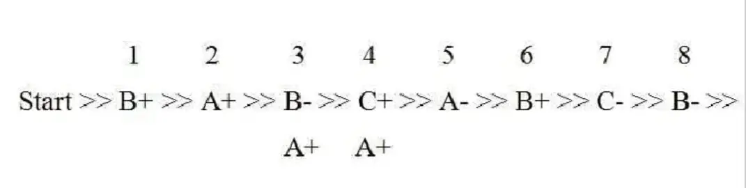
Here, the cylinder clamps the workpiece throughout the arm’s return movement and the suction gripping process, so A+ is performed in parallel with B- and C+ in stages 3 and 4.
* Step 2: Program the temporary memory bits to remain energized (the stages)
The stages here are the temporary memory bits M.
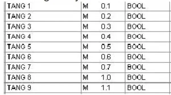
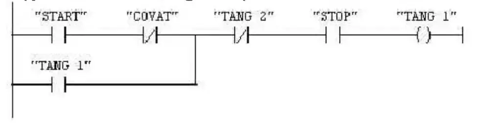
Stage 1 starts when an object is detected by sensor COVAT (a normally closed NC contact) AND the Start button is pressed.
Stage 1 ends when stage 2 starts OR the Stop button (normally closed - NC) is pressed. We must take the NEGATION of the stage-ending condition to use it in the ladder diagram.
The network for stage 1 is therefore written as follows:
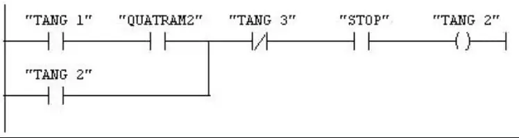
Similarly, stage 2 starts when stage 1 is active and transfer arm B has reached station 2 (actuating limit switch QUATRAM2).
Stage 2 ends when stage 3 starts or the Stop button is pressed. The network for stage 2 is as follows:
Similarly, stage 3 starts when stage 2 is active and the workpiece-pushing cylinder has pushed the workpiece out to the pickup position and is clamping it there (sensor KEP is actuated).
Stage 3 ends when stage 4 starts or the Stop button is pressed. The network for stage 3 is as follows:
You can easily see that only one stage is active at any given time. When stage 2 becomes active, it deactivates stage 1 (the preceding stage). When stage 2 is complete (the cylinder has finished pushing out the workpiece), stage 3 starts and deactivates stage 2.
You can also easily see that these networks are very similar, so you only need to Copy, Paste, and Edit them as appropriate (remember to edit carefully; if you miss something or make a mistake, the program will not run).
Do the same for the other networks and stages.
* Step 3: Combine the stages to control the actuators
Suppose we assign the following symbols to the actuators:
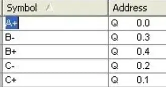
In the sequence defined in step 1, we can see that action A+, which operates the cylinder to push out the workpiece and clamp it in position, is performed in stages 2, 3, and 4. We therefore have the following network:
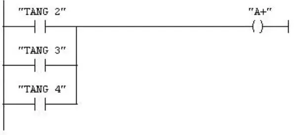
Here, A+ is a PLC output that energizes the coil responsible for pushing out the workpiece.
Action A- in stage 5 does not require activating any output, because simply cutting power to coil A+ makes the cylinder retract automatically.
Action B- must be performed in stages 3 and 8, so we have the following network:
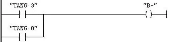
Continue with all the other actuators.
Conclusion:
Your program is now complete. It does not use a single Set or Reset operation, yet it is still logical and well structured. And I assure you that it can run properly, too!
Give it a try, especially if you are taking MPS practical training. And let me know the results. This took a lot of effort to write, so I would like to know whether it has helped you! And if anything is incorrect or could be improved, I would like to know where so I can revise it. If you support this, I will write about some other topics as well, such as PCS or AVR microcontrollers…
Written by: Nguyễn Công / Posted by xuanhieuute.com on 11/3/2013 / Edited to restore missing images 3/8/2022
Bài liên quan
- FlexSim Simulation Software - CIM Practicum
- "Conversation with Thanh" Nguyễn Thành Nam: When the essence of liberation slips into the frivolity of history
- Bypass AI content: make AI writing sound more natural
- Download Comet Perplexity AI Browser (Latest 2026): Official Links & How to Get an Invite Code Instantly
- Khao Man Gai: Secrets to Authentic Thai Flavor at Home!
- Thai-Style Steamed Fish with Lime and Garlic: Delicious, Healthy, and Easy to Make at Home!
- Khao Man Gai: A Journey to Discover Thailand’s Famous Chicken Rice!
- Cafe Amazon Bangkok 2026: Latest Menu & Prices!